Tricorder Tech: Quantum Sensing In Your Pocket

Editor’s note: If you have seen a Tricorder on Star Trek then you know it pretty much answers a wide range of questions. It tells you about the planet you are on, what life forms may or may not be there, and if need, be how your body is doing as you walk around on a strange new world. That’s a lot of computation and senor capability in a small package. But if you are on an Astrobiology Away Team you might just want to have things like this. According to one of the researchers: “You could imagine using this technology being added to smartphones to help with remote medical diagnostics, or identifying defects in materials.”
—–
Smartphones could one day become portable quantum sensors thanks to a new chip-scale approach that uses organic light-emitting diodes (OLEDs) to image magnetic fields.
Researchers from the ARC Centre of Excellence in Exciton Science at UNSW Sydney have demonstrated that OLEDs, a type of semiconductor material commonly found in flat-screen televisions, smartphone screens and other digital displays, can be used to map magnetic fields using magnetic resonance.
Sensing of magnetic fields has important applications in scientific research, industry and medicine.
Published in the prestigious journal Nature Communications, this technique is able to function at microchip scale and – unlike other common approaches – does not require input from a laser.
The majority of existing quantum sensing and magnetic field imaging equipment is relatively large and expensive, requiring either optical pumping (from a high-powered laser) or very low cryogenic temperatures. This limits the device integration potential and commercial scalability of such approaches.
By contrast, the OLED sensing device prototyped in this work would ultimately be small, flexible and mass-producible.
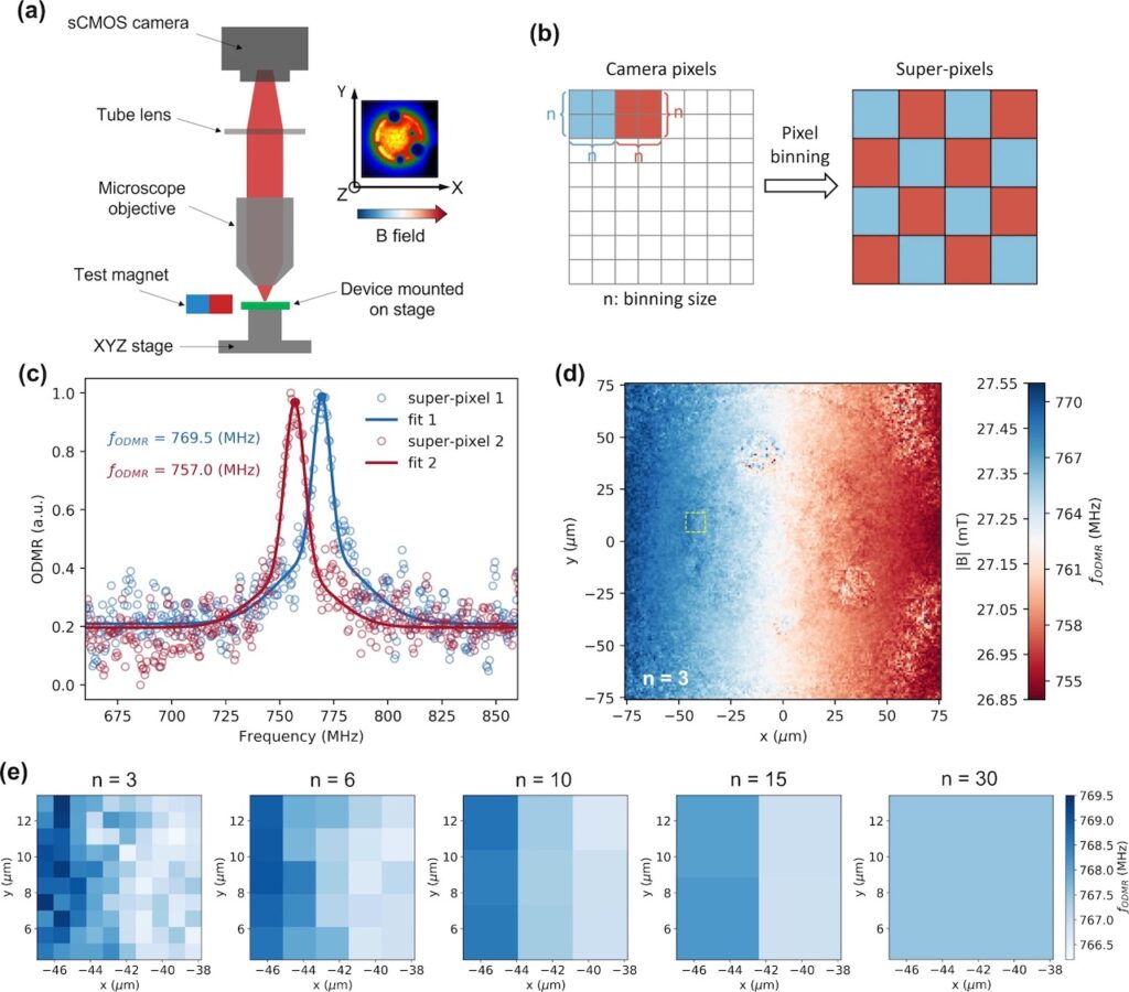
The techniques involved in achieving this are electrically detected magnetic resonance (EDMR) and optically detected magnetic resonance (ODMR). This is achieved using a camera and microwave electronics to optically detect magnetic resonance, the same physics which enables Magnetic Resonance Imaging (MRI).
Using OLEDs for EDMR and ODMR depends on correctly harnessing the spin behaviour of electrons when they are in proximity to magnetic fields.
OLEDs, which are highly sensitive to magnetic fields, are already found in mass-produced electronics like televisions and smartphones, making them an attractive prospect for commercial development in new technologies.

Professor Dane McCamey of UNSW, who is also an Exciton Science Chief Investigator, said: “Our device is designed to be compatible with commercially available OLED technologies, providing the unique ability to map magnetic field over a large area or even a curved surface.
“You could imagine using this technology being added to smartphones to help with remote medical diagnostics, or identifying defects in materials.”
First author Dr Rugang Geng of UNSW and Exciton Science added: “While our study demonstrates a clear technology pathway, more work will be required to increase the sensitivity and readout times.”
Professor McCamey said that a patent has been filed (Australian Patent Application 2022901738) with a view toward potential commercialisation of the technology.
Sub-micron spin-based magnetic field imaging with an organic light emitting diode, Nature Communications (open access)
Astrobiology


